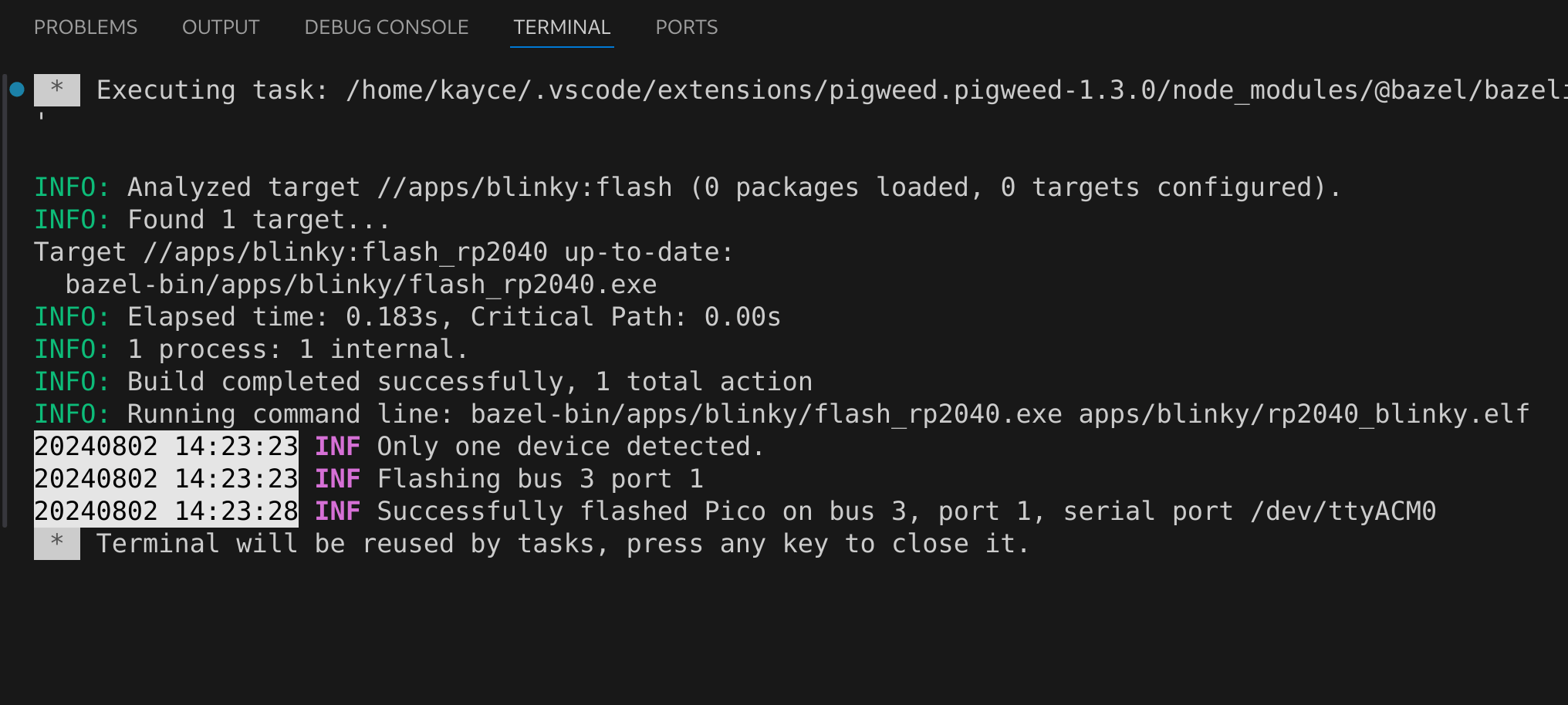
1.. _showcase-sense-tutorial-flash: 2 3================== 47. Flash your Pico 5================== 6Enough with the simulations. Let's work with some real hardware! 7You'll need a physical Raspberry Pi Pico for the rest of the tutorial. 8You can use any version of the Pico: Pico 1, Pico 1W, Pico 2, or Pico 2W. 9We support them all. 10 11.. _showcase-sense-tutorial-hardware: 12 13-------------------- 14Set up your hardware 15-------------------- 16Follow the instructions in one of the following tabs (**Full setup**, 17**Pico and Enviro+**, or **Pico only**) to set up your hardware. 18The full setup provides the most robust experience. Some later pages 19in the tutorial require the full setup. 20 21.. tab-set:: 22 23 .. tab-item:: Full setup 24 25 .. _Pico: https://www.raspberrypi.com/documentation/microcontrollers/pico-series.html 26 .. _Enviro+ Pack: https://shop.pimoroni.com/products/pico-enviro-pack 27 .. _Debug Probe: https://www.raspberrypi.com/products/debug-probe/ 28 .. _Omnibus: https://shop.pimoroni.com/products/pico-omnibus 29 30 In the full setup, you combine a `Pico`_, `Enviro+ Pack`_, `Debug Probe`_, and 31 `Omnibus`_. The Debug Probe provides more robust flashing and debugging. 32 The Omnibus provides the Debug Probe access to the Pico's UART pins. 33 These UART pins aren't accessible when a Pico is connected directly to an 34 Enviro+. 35 36 By the end of the instructions your full setup will look similar to this: 37 38 .. figure:: https://storage.googleapis.com/pigweed-media/sense/full_setup_zoom_v1.jpg 39 40 **Update the Debug Probe firmware** 41 42 .. _Update the Debug Probe firmware: https://www.raspberrypi.com/documentation/microcontrollers/debug-probe.html#updating-the-firmware-on-the-debug-probe 43 44 #. Connect the Debug Probe to your development host over USB. 45 46 #. `Update the Debug Probe firmware`_. You just need to download the latest 47 release and drag-and-drop the UF2 file onto your Debug Probe. You 48 want the ``debugprobe.uf2`` file from the releases page. It only 49 takes a minute or two. 50 51 **Omnibus setup** 52 53 #. Connect the Enviro+ to **Deck 1** on the Omnibus. 54 55 #. Connect the Pico to the middle landing area on the Omnibus. 56 57 .. important:: 58 59 Make sure that the Pico's USB port lines up with the **USB** 60 label on the Omnibus. 61 62 .. figure:: https://storage.googleapis.com/pigweed-media/sense/omnibus_v1.jpg 63 64 **Serial Wire Debug port setup** 65 66 .. _JST-SH: https://cdn-shop.adafruit.com/970x728/5765-01.jpg 67 68 #. Find the Serial Wire Debug (SWD) port on your Pico. On the Pico 1 and 69 Pico 2 the SWD port is at the edge of the board. On the Pico 1W and 70 Pico 2W it's near the middle of the board. The front of the Pico (the side 71 with the raspberry logo) has a **DEBUG** label close to the port. 72 73 #. Determine if your Serial Wire Debug (SWD) port has male or female connectors. 74 75 If it's male, follow the instructions in the **Male** tab in the next step. 76 If female, use the **Female** tab instructions. 77 78 .. figure:: https://storage.googleapis.com/pigweed-media/sense/swd_v1.jpg 79 80 #. Connect the SWD port on your Debug Probe to the SWD port 81 on your Pico. 82 83 .. tab-set:: 84 85 .. tab-item:: Male 86 :sync: male 87 88 #. Connect the inner cable of the Debug Probe (SC) to the **SWCLK** 89 pin on the Pico's debug port. The back of the Pico 90 (the side that does not have the raspberry logo) has a **SWCLK** 91 label showing the location of that pin. 92 93 .. tip:: 94 95 The image caption below provides an example of what we mean 96 by "inner cable" (as well as "middle" and "outer"). The colors on these 97 types of cables aren't standardized, so we had to think up a 98 different way to describe them. 99 100 #. Connect the middle cable (ground) to the **GND** pin on the 101 Pico's debug port. 102 103 #. Connect the outer cable (SD) to the **SWDIO** pin on the Pico's debug port. 104 105 .. figure:: https://storage.googleapis.com/pigweed-media/sense/debug_male_v1.jpg 106 107 .. figure:: https://storage.googleapis.com/pigweed-media/sense/debug_male_zoom_v2.jpg 108 109 In these images the "inner" cable is the white cable, the red cable is the "middle" 110 cable, and the black cable is the "outer" cable. 111 112 .. tab-item:: Female 113 :sync: female 114 115 #. Connect the **DEBUG** port on the Pico with the 116 **DBUG** port on the Debug Probe using the `JST-SH`_ 117 to JST-SH cable. JST-SH connectors only fit in one direction. 118 119 .. figure:: https://storage.googleapis.com/pigweed-media/sense/debug_v3.jpg 120 121 **UART setup** 122 123 #. Connect the inner cable (RX, input to Debug Probe) to pin **0** 124 on **Deck 2** of the Omnibus. 125 126 #. Connect the outer cable (TX, output from Debug Probe) to pin **1** 127 on **Deck 2** of the Omnibus. 128 129 #. Connect the middle cable (ground) to any of the pins labeled with a long dash (**—**) 130 on **Deck 2**. 131 132 .. figure:: https://storage.googleapis.com/pigweed-media/sense/uart_v1.jpg 133 134 .. figure:: https://storage.googleapis.com/pigweed-media/sense/uart_zoom_v1.jpg 135 136 In the previous 2 images the "inner cable" is the yellow cable, the "middle" 137 cable is the black cable, and the "outer" cable is the orange cable. 138 139 .. note:: 140 141 The Serial Wire Debug port connections from the last section 142 are omitted from the previous two images to help you focus on the new 143 UART cable connections. Don't remove your SWD port connections. 144 145 **USB setup** 146 147 #. Hold down the **BOOTSEL** button on the front of your Pico (the side 148 with the raspberry logo) to prepare the Pico for flashing. 149 150 #. While still holding down **BOOTSEL**, connect your Pico to a USB port on your development host 151 or to a separate power supply. 152 153 .. tip:: 154 155 Connecting to a separate power supply will slightly simplify the flashing 156 process later. 157 158 #. Connect your the USB Micro-B port on your Debug Probe to a USB port on your 159 development host. If you updated the Debug Probe firmware earlier, your Probe 160 may already be connected to your host. 161 162 You're done! Your setup should look similar to this: 163 164 .. figure:: https://storage.googleapis.com/pigweed-media/sense/full_setup_v1.jpg 165 166 .. tab-item:: Pico and Enviro+ 167 168 #. Connect the Pico to the Enviro+ Pack. 169 170 #. Hold down the **BOOTSEL** button on the front of your Pico (the side 171 with the raspberry logo) to prepare the Pico for flashing. 172 173 #. While still holding down **BOOTSEL**, connect your Pico to a USB port on your development host. 174 175 .. figure:: https://storage.googleapis.com/pigweed-media/sense/basic_enviro_front_v1.jpg 176 177 .. figure:: https://storage.googleapis.com/pigweed-media/sense/basic_enviro_back_v1.jpg 178 179 .. tab-item:: Pico only 180 181 #. Hold down the **BOOTSEL** button on the front of your Pico (the side 182 with the raspberry logo) to prepare the Pico for flashing. 183 184 #. While still holding down **BOOTSEL**, connect your Pico to a USB port on your development host. 185 186 .. figure:: https://storage.googleapis.com/pigweed-media/sense/basic_v1.jpg 187 188.. _showcase-sense-tutorial-udev: 189 190----------------- 191Set up udev rules 192----------------- 193#. Configure your host to properly detect Raspberry Pi hardware. 194 195 .. tab-set:: 196 197 .. tab-item:: Linux 198 199 #. Add the following rules to ``/etc/udev/rules.d/49-pico.rules`` or 200 ``/usr/lib/udev/rules.d/49-pico.rules``. Create the file if it doesn't 201 exist. You will probably need superuser privileges (``sudo``) to create 202 or edit this file. 203 204 .. literalinclude:: /targets/rp2040/49-pico.rules 205 :language: linuxconfig 206 :start-at: # Raspberry 207 208 #. Reload the rules: 209 210 .. code-block:: console 211 212 sudo udevadm control --reload-rules && sudo udevadm trigger 213 214 #. If your Pico is already connected to your host, unplug it and plug 215 it back in again. Hold down the **BOOTSEL** button on the front of 216 the Pico while plugging it back in to ensure that the Pico is ready 217 for flashing. 218 219 .. tab-item:: macOS 220 221 No extra setup needed. 222 223.. _showcase-sense-tutorial-flash-blinky: 224 225---------------------------------------- 226Flash an application binary to your Pico 227---------------------------------------- 228#. Flash the ``blinky`` bringup program to your Pico. 229 230 .. tab-set:: 231 232 .. tab-item:: VS Code 233 :sync: vsc 234 235 #. In **Bazel Targets** expand **//apps/blinky** and find your board's 236 target: 237 238 * If your board is a Pico 1 or Pico 1W then your board's target 239 is **flash_rp2040**. 240 241 * If your board is a Pico 2 or Pico 2W then your board's target 242 is **flash_rp2350**. 243 244 RP2040 is the name of the MCU that powers first-generation 245 Picos. The RP2350 powers second-generation Picos. 246 247 #. Right-click your board's target then select **Run target**. 248 249 #. If you've connected both the Debug Probe and Pico to your host over USB, 250 you'll see the following prompt. (If your Pico is connected to a separate 251 power supply, you won't see this prompt and can ignore this part.) Select 252 **Raspberry Pi - Debug Probe (CMSIS-DAP)**. 253 254 .. code-block:: console 255 256 Multiple devices detected. Please select one: 257 1 - bus 3, port 1 (Raspberry Pi - Debug Probe (CMSIS-DAP)) 258 2 - bus 3, port 6 (Raspberry Pi - Pico) 259 260 In this example you would want to select ``1``. 261 262 A successful flash looks similar to this: 263 264 .. figure:: https://storage.googleapis.com/pigweed-media/sense/20240802/flash.png 265 266 .. tab-item:: CLI 267 :sync: cli 268 269 #. Flash your Pico. 270 271 .. tab-set:: 272 273 .. tab-item:: Pico 1 & 1W (RP2040) 274 :sync: rp2040 275 276 .. code-block:: console 277 278 bazelisk run //apps/blinky:flash_rp2040 279 280 .. tab-item:: Pico 2 & 2W (RP2350) 281 :sync: rp2350 282 283 .. code-block:: console 284 285 bazelisk run //apps/blinky:flash_rp2350 286 287 #. If you've connected both the Debug Probe and Pico to your host over USB, 288 you'll see the following prompt. (If your Pico is connected to a separate 289 power supply, you won't see this prompt and can ignore this part.) Select 290 **Raspberry Pi - Debug Probe (CMSIS-DAP)**. 291 292 .. code-block:: console 293 294 Multiple devices detected. Please select one: 295 1 - bus 3, port 1 (Raspberry Pi - Debug Probe (CMSIS-DAP)) 296 2 - bus 3, port 6 (Raspberry Pi - Pico) 297 298 You should see output like this: 299 300 .. code-block:: text 301 302 20241220 19:46:38 INF Flashing bus 3 port 6 303 304The LED on your Pico should start blinking on and off at a 1-second interval. 305 306.. admonition:: Troubleshooting 307 308 If you see ``A connected device has an inaccessible serial number: The 309 device has no langid (permission issue, no string descriptors supported or 310 device error)`` it probably means you need to update your udev rules. See 311 :ref:`showcase-sense-tutorial-udev`. 312 313 If you see ``Error: Connecting to the chip was unsuccessful`` or 314 ``ERROR: This file cannot be loaded into the partition table on the device``, 315 make sure that you're using the correct flashing target. These errors suggest 316 that you tried to use the Pico 1 target on a Pico 2 board, or vice versa. 317 318.. _showcase-sense-tutorial-flash-summary: 319 320------- 321Summary 322------- 323.. _target: https://bazel.build/concepts/build-ref#targets 324 325In a Bazel-based project like Sense there is no separate flashing 326process. Flashing is a Bazel target, just like building and testing 327the source code are Bazel targets. Your team can manage all core 328development workflows through Bazel. 329 330Next, head over to :ref:`showcase-sense-tutorial-devicetests` to 331try out on-device unit tests. 332